EYE ON . EMC is a complex topic. To achieve the desired EMC characteristics of a product, in an efficient way, often requires collaboration between different professional groups. In addition to electronics designers, all parties involved should have the understanding and basic knowledge of the subject. The most concerned may be: mechanical designers, project managers, machine builders, installers, and others.
Ground plane
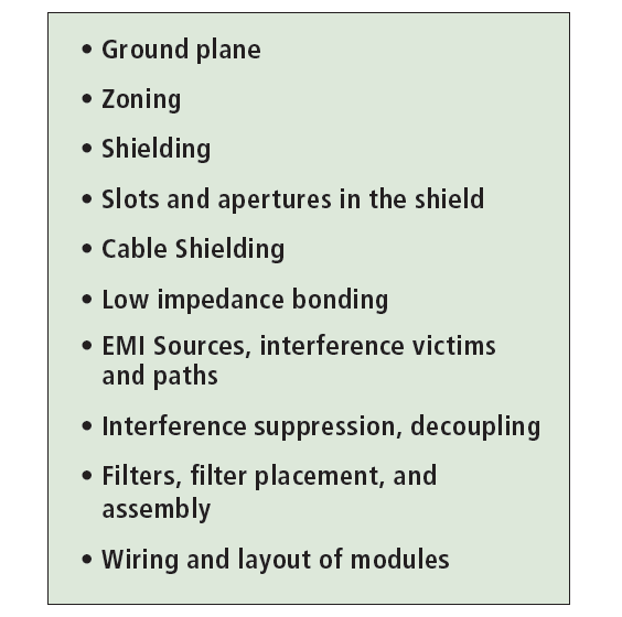
To facilitate this collaboration, I will in this and future articles explain these concepts. See Figure 1.

GROUND PLANE
It is one of the most important concepts in EMC. Ground plane is good! Create ground plane! Create one common ground plane!
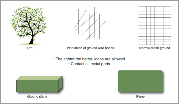
All materials with good conductivity (low impedance) can act as a ground plane at all frequencies, provided the plane is wider than the projected area of the circuit or the apparatus it is supposed to shield. The circuit or apparatus should also be placed as close to the plane as possible. A ground plane need not be plane, it may assume any shape. “Ground plane” in this context means also bounded electrically conductive structures. See figure 2.
In order to ensure that a ground plane obtains low impedance (in the entire frequency range of EMC), if the ground plane consist of more than one pies of metal, it must have as many and broad parallel bonds between parts as possible. (Many large conductive surfaces mating in the bond.)

A metal structure which surrounds, or is carrier of the electric and electronic circuits of the device, is sometimes called chassis ground. In practice the chassis ground is regarded as an extension of a circuit ground plane. Note that “ground” by definition is the metallic part of the shield! Examples of ground planes: unbroken copper layers in a printed circuit board, unit housings, chassis or rack, shielding plate, cable shield, cohesive installation mechanics and so on.
Advantages of a ground plane:
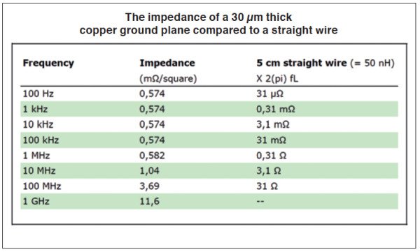
- very low intrinsic impedance (inductance), see Figure 3.
- acts as “generic shield” (is part of as mentioned above)
- reduces mutual impedance
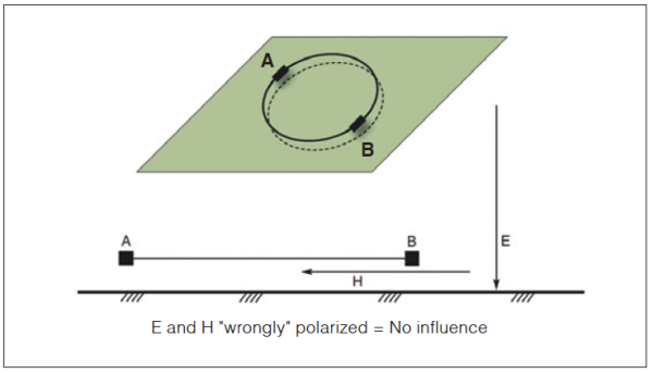
- reduces field coupling, crosstalk as well as far field, see Figure 4.
- enables grounding for filtering and decoupling (a shield is needed for filters).


Miklos Steiner, Ulf Nilsson
info@justmedia.se


