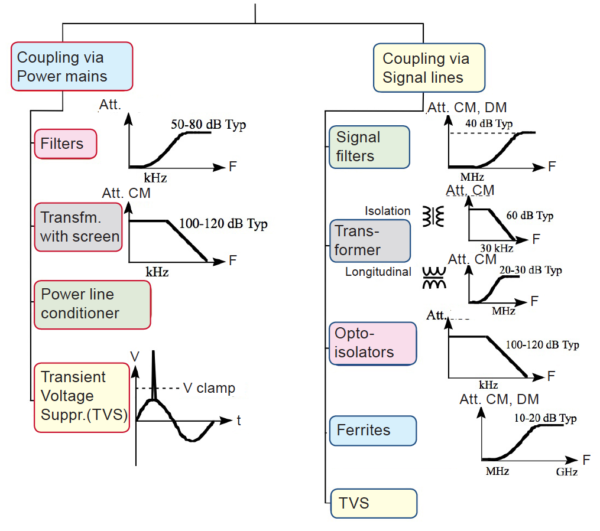
Our former . eight EMC articles were aimed at familiarizing unaware readers with the fundamentals of EMI/EMC, justifying the EMC norms and testing, and explaining in simple terms the five basics interference coupling mechanisms, with the essential guidelines for controlling them. The present article goes deeper into one of the simplest, most compact and economical piece of the entire EMC arsenal: the filter. With current handling ranging from tens of Amp for signal filters up to more than hundred Amps for power line filters, they exist in all sorts of size, volume and packaging. They can be optimized against Common Mode (CM) or Differential Mode (DM) interference, or both.
No matter if you plan to buy a commercial, off-the shelf (COTS) or make your own, you must understand how they work and how to determine the most adequate arrangement of L,C elements. A filter should not be picked-up off an EMC guru’s tool case: it must be designed. Finally, although regarded as a cure against conducted EMI, filters can also reduce radiated interference, for Emission or Susceptibility.

2. Selecting the right filter
Given that an EMI filter is a low-pass element, the following parameters dictate its choice :
a) the required attenuation (DM/CM) for a given frequency, rigorously termed Insertion Loss (IL) *
b) the cut-off frequency
c) the number of poles, which itself depends on a) and b)
d) the impedances on the source and load sides of the filter, that in turn will guide the filter scheme
e) type of filter: simple capacitor, simple inductor, L-C, Tee or Pi
f) the normal service voltage/ current, to be considered for the…
Dear colleague,
This text is unfortunately locked for further reading, but you can read all Michel Mardiguian’s texts and course material about EMC in the new book “Everything you always wanted to know about EMC but were afraid to ask”. Click for more information!


